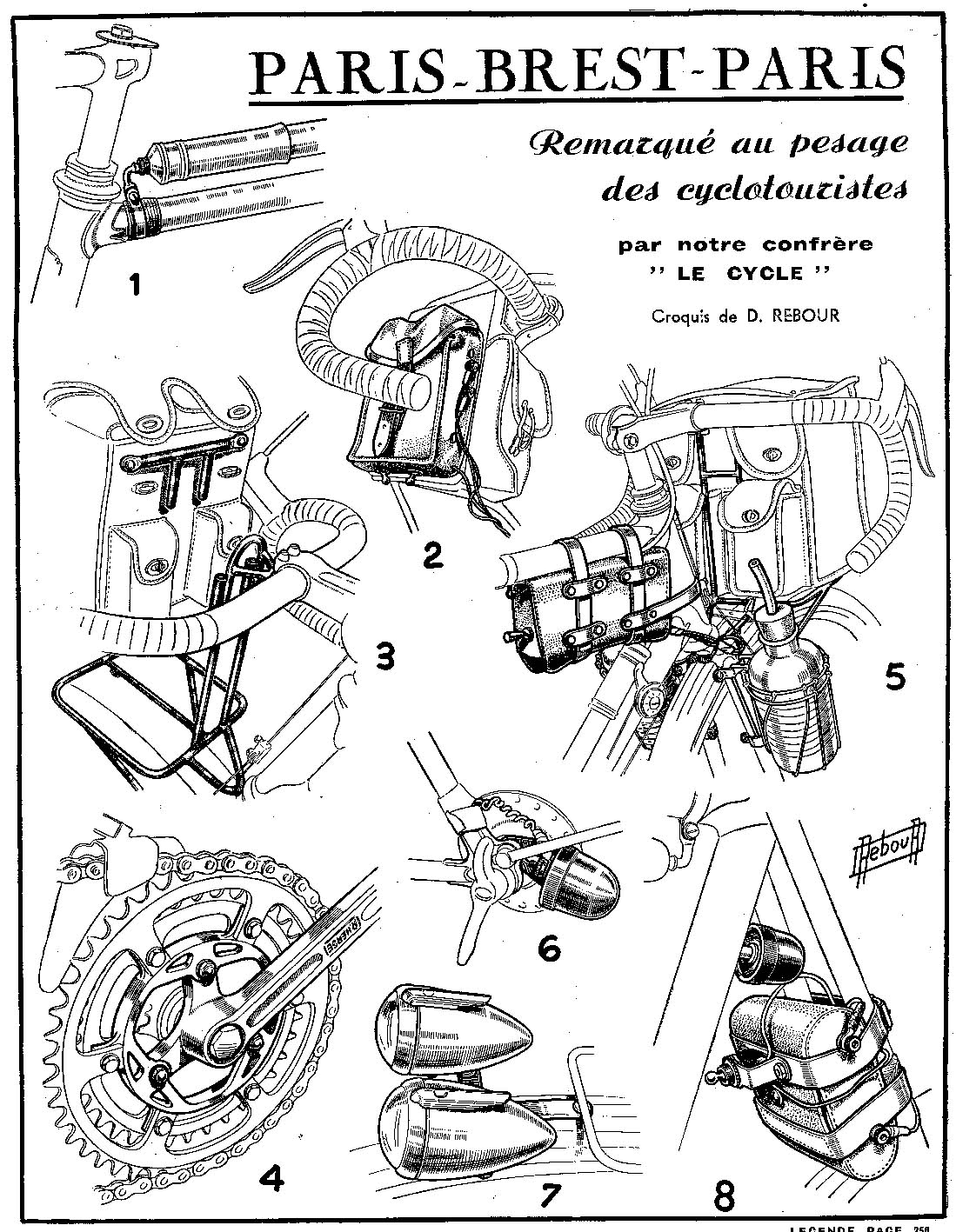
1: stella (no. 392) : the pump is attached with clips on the top tube. this allows using bottle cages on the frame.
2: singer (no. 29) : the little left pocket of the handlebar bag held a standard battery: we see the two switches at the bottom, which control the headlight and red taillight.
3: handlebar bag support herse, which completely frees the handlebars from straps. one piece, which forms a "t," is rivetted at both ends to the bag and is placed in two tubes of the rack. the bag can be removed and installed instantaneously. a hook with a spring locks it to the bottom. the rider thus has a bag that is attached rigidly and will not move when the bike corners. (ed. note: this was one of the first of this type of design, used on this renť herse. later, other makers more or less copied it. the lower hook was found unnecessary - friction in the two tubes holds the bag in place.)
4: ta "adapteur" for herse cranks, with 44 x 36 chainwheels.
5: herse (no. 182) the rider made his own electric equipment, with a standard battery. the switch allows going from battery lighting (used on the long and steep hills) to generator lighting without stopping. we note the location of the two bottles, which are attached to the fork legs. after three years and many long rides, these are found to be the best possible placement, with no impact on steering or pedaling.
6-7-8: herse (no. 189) electrical equipment "maison" (made by herse): the standard battery, with a switch, is attached to the seatstays and rests on the fender. the twin radios headlights are connected as follows: one to the generator, the other to the battery. the normal taillight is attached under the seat (ed. note: probably on the rear of the seat tube, as was common herse practice), powered by the generator. the battery powers another taillight that is attached at the dropout underneath the eyebolt for the fender stay.